Self-levitating motor 101
…or can work. Remember the recent post about active magnetic bearings? Put shortly, they can use magnetic forces to levitate the shaft (and rotor of course) of an electric motor, reducing friction and keeping compressed air oil-free, for example.
However, one might wonder…
After all, the motor itself already is using magnetic forces to produce torque. So could these forces be reconfigured to levitate the rotor at the same time, without needing a separate bearing assembly?
The answer, unsurprisingly, is yes.
Now, let’s see how.
Levitation briefly
Everybody knows how a magnet (permanent or electro-, matters not) attracts iron. Well, the same thing is also happening in the airgap of an electric motor, too. At any point in the airgap, the stator and rotor surfaces are being pulled towards each other.
However, in a well-designed machines the total forces typically cancel each other. (You might see exceptions in flux-switching machines and similar, where compromises may have to be made between nice waveforms etc.) This is to prevent high forces on conventional bearings, which would drastically limit their lifespan.
Now, however, we are speaking about a bearingless machine, so a total force is indeed desirable. And it turns out, by simply changing the machine design, we can achieve it quite neatly, and make the rotor levitate
Next, let’s see how exactly that happens.
Levitation not-so-briefly
Of course, we don’t simply want some force acting on the rotor. We want a rather precise level of force, cancelling the gravity and nothing more. In other words, we want the force to be controllable.
For this purpose, a self-levitating motor usually has two sets of windings. The first one is the typical three-phase winding, responsible for the torque production. The second one is a small additional winding, generating the levitation force. Often, this additional winding can be quite small, perhaps occupying only 10 % of the total slot area.
The operating principle is actually quite close to the biased active magnetic bearing that was described earlier. Only now, the main winding is acting as the bias winding, while the additional winding takes the role of the control winding.
Details
To really make things work, there are a few quirks. First of all, the control really needs to be nailed in. After all, the ‘bias’ winding is now producing a rotating field, rather than a nice static field as in the case of an AMB. Additionally, the rotor slotting / PMs / flux barriers will produce force/torque ripple and other second-order effects to be dealt with.
Importantly, the pole number of the additional winding must differ by two from the pole number of the main winding. So, for a four-pole machine, the levitation winding can have either two or (less commonly) six poles.
There are two ways to see how this works.
Visual explanation
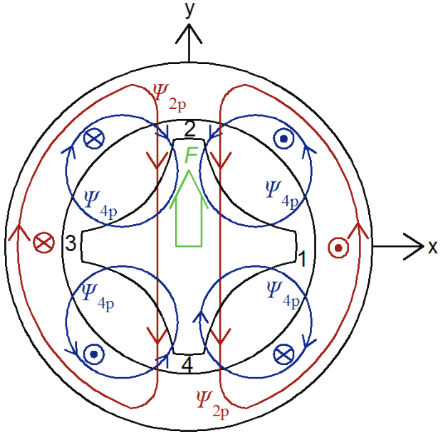
The first one is to actually see it from the figure below.

The figure above represents a four-pole synchronous reluctance motor. The flux generated by the main winding is illustrated with blue. By contrast, the red lines represent the additional winding flux.
As you can see (repeating myself enough yet?), the fields from the main and additional winding are adding up on the top of the rotor, and opposing each other on the bottom. So, we end up with a stronger field above-side. And, since any field between two lumps of iron basically results in some ‘force density’ (aka stress), we now get a nice net force upwards. This happens due to the now-unsymmetrical force distribution – the forces are no longer cancelling each other out.
Mathematical explanation
The same result can be derived with pure equations, too. Let’s write the airgap field as
![]() ,
,
where ![]() is the angular coordinate.
is the angular coordinate. ![]() and
and ![]() , on the other hand, are the amplitudes of the main and additional winding field fundamentals, with
, on the other hand, are the amplitudes of the main and additional winding field fundamentals, with ![]() and
and ![]() pole pairs, respectively.
pole pairs, respectively.
On the other hand, from Maxwell’s stress tensor we know that the force “density” is proportional to the square of the flux density amplitude. So, we can get the total x- and y-directional forces from
![]()
![]() .
.
Now, we substitute the two flux waves defined earlier for ![]() , and then expand the trigonometric triple-products by using the well-known product formula twice. What we see is, indeed, that the pole-pair numbers
, and then expand the trigonometric triple-products by using the well-known product formula twice. What we see is, indeed, that the pole-pair numbers ![]() and
and ![]() have to differ by one for any net force to be produced:
have to differ by one for any net force to be produced:
![]() .
.
By the way, this is a very good result to bear in mind, even if building a bearingless motor is not your goal. Particularly, when designing flux-switching or switched reluctance machine, you should check if there are unbalanced forces produced. The pole-pair number-check described earlier does exactly that.
Benefits and drawbacks
So far, I’ve yet to read a comprehensive analysis of the pros and cons of using self-levitation instead of dedicated AMBs. Not that I’ve looking for one, either. But I digress. Nevertheless, here are some thoughts of mine (and others’, that I’ve picked up along the way) regarding the relative benefits and drawbacks:
(+) Compact design: no need for a separate bearings assembly.
(-) Decreased space for main winding: the additional winding takes room for itself, leaving less to be used for torque production.
(+) Increased active length: On the other hand, not needing a separate bearing makes for a longer core, resulting in more torque.
(-) More difficult control.
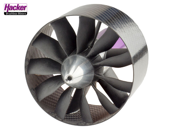
(+) Near-perfect fit for some applications: A ducted fan springs to mind, with the stator located on the fan periphery, and the rotor-fan levitated in the middle.
(-) Poor axial force capacity: Our previous ducted-fan example would definitely need a special design for this reason.
(-) Control of conical vibrations: Preventing the rotor from wobbling might be difficult.
(-) Uneven flux density: More flux is needed on the ‘up’ side to counteract gravity.
(-/neutral) The effect of said flux density on iron losses: The uneven part is largely DC, so it might not be as problematic as it seems.

Conclusion
- How an active magnetic bearing system can be incorporated into an electric motor itself.
- Some benefits and drawbacks.
- My colleague is an expert on the topic.
Check out EMDtool - Electric Motor Design toolbox for Matlab.
Need help with electric motor design or design software? Let's get in touch - satisfaction guaranteed!
