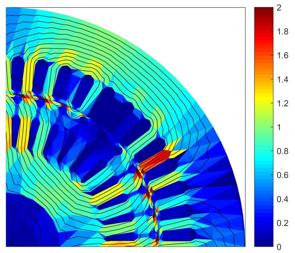
Illustration of circulating and eddy currents with PWM supply
Recently, I gave a lecture for a course on model order reduction for electrical machines. My part focussed on windings, and also included some computer exercises. Here we analysed a motor with stranded winding, with several different winding configurations and supply waveforms. Based on the material, I made the following nice little video.
This post will cover lots of miscellaneous background information. Included are
- The motor analysed
- Description of winding
- Method of analysis
- Voltage waveforms
- Explanation of the video
- Simulated losses
- Limitations and caveats
Without further rambling, here goes.
Machine analysed
The examples focused on a 37 kW induction machine. It’s been sitting in our lab for ages, and has thus been involved in more papers than most researchers could dream about. The students then changed the exact winding configuration this way and that, and simulated what happens.

The original machine had a star-connected winding, intended for 400 V line-to-line voltage. However, for the animation it was converted into a low-voltage machine by changing the winding to delta connection, and dropping the number of turns from 12 to 2. Around 38 V rms in other words, or 55 peak.
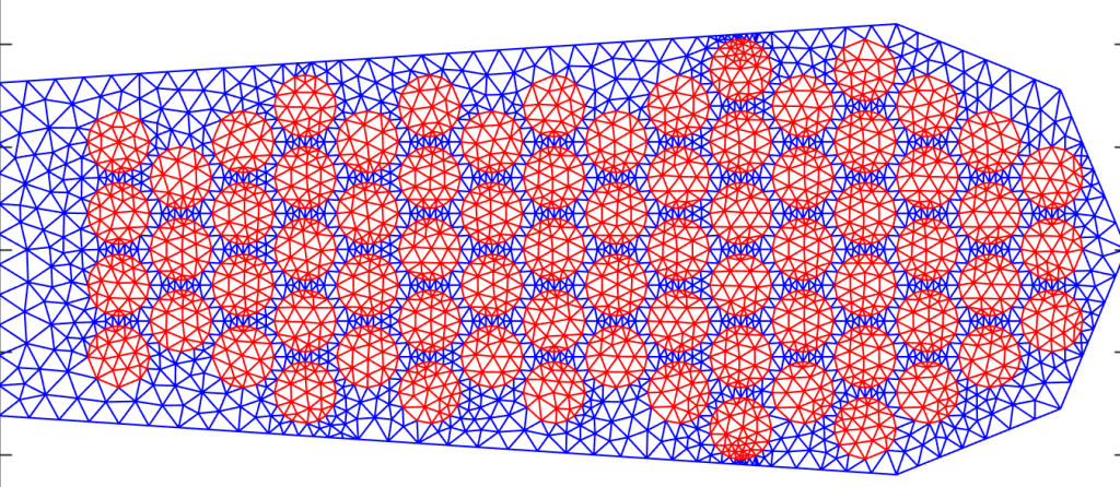
In the examples, the winding was wound from 1.2 mm copper wire, with 72 strands in each slot. As the machine had a single-layer winding, there was no chording.

Method of analysis
The motor was then analysed with 2D nonlinear time-stepping FEA (using SMEKlib, no surprise), with the rotor moving at a constant slip. Nothing too fancy here (although time-stepping is already semi-fancy for many, in my experience).
However, the interesting part here is how the windings were analysed. Unlike usually, the stranded winding of the machine was actually modelled as stranded. Meaning, circuit equations were written (or rather, compiled automatically) for all the strands in the motor. So, for the original design of six wires-in-hand per each phase, a total of 18 current paths were modelled. Finally, voltage supply was used, meaning no magically imposed currents.
A full eddy-current model was used for the winding. A so-called macro-element approach was used to get precise results fast enough, meaning around ~5 s per 200 time-steps on the classroom computers. To give you some reference, a standard eddy-current simulation would probably have taken minutes if not hours, and still yielded the same results (minus some numerical errors of course).
Supply
Two different voltage waveforms were compared. The first was pure sinusoidal three-phase supply, the kind you get from the grid (and textbooks).
The second one was simple PWM, obtained with the sine-triangle method. The DC-link voltage was 60 V, and the swithing frequency was only 1 kHz. The fundamental amplitude was the same as with sinusoidal supply, but no active control was otherwise used.
What happens in the video
Before we go into the details, let’s put the animation here again. That way, you won’t have to scroll back and forth so much.
As you remember, each slot had 72 strands of 1.2 mm wire. However, since the number of turns was only 2, this translates to 36 wires-in-hand. Meaning, each turn is composed of 36 wires connected in parallel at the terminals. In the geometry above, the 36 wires closest to the slot bottom form the first turn, and the remaining ones the second.
Circulating currents, again
In the worst case, a stranded winding like this could suffer from very high circulating currents, meaning those wires closer to the slot opening would carry much larger currents than those closer to the bottom, in each turn. This phenomenon is caused by the slot leakage flux, leading to each strand seeing a different induced voltage depending on their position inside the slot. So, almost like the skin effect in a solid slot-bound conductor.
In practice, a few factors limit the severity of the phenomenon.
Firstly, a random winding is really random to a degree. Meaning, a strand at the top of a turn (=worst position) in slot 1 might be closer to the bottom in slot 13 (=better position), cancelling out some of the voltage differences and thus leading to a more even distribution of current.
Secondly, a similar phenomenon can be induced by manufacturing techniques, too. Large generators use Wroebel bars to change the strand positions inside one slot along the length of the machine, but this is not feasible in a smaller, cheaper motor. Instead, the order of the strands can be changed in the end-winding region, between two successive slots. Commonly, this is done by dividing each turn in a number of smaller bundles, and then changing their order. So is the case in the example, too.
Video, for the umpteenth time
So, finally, what really happens in the video?
The color scale represents current density inside the wires. If you look closely, you can see some variation inside individual wires – those are the well-known eddy currents at work!
However, especially with PWM supply you also notice huge differences in the overall color level of different wires. What you see are in fact the circulating current effect – different wires carrying different currents. As the losses are proportional to current squared, they are of course thus increased.
What happens inside the winding is basically this. Any time the inverter switches the voltage of phase A, the phase current starts changing rapidly. Thus, also the slot leakage flux starts to change. Now, the parallel strands in the phase basically form a short circuit loop that links the slot flux. So, naturally, such currents will start to flow that oppose the change. In other words, the total phase current gets concentrated towards either the slot opening or bottom, depending on the sign of the voltage change. As this happens inside all turns (and wire bundles), a clear jump in the current level can be seen between them.
Simulated losses
To keep things simple, the students focused only on the circulating current losses. In other words, the current density inside each strand was assumed uniform. Thus, the winding losses could be computed from the strand resistances in the post-processing stage.
For the sinusoidally-fed machine, nothing catastrophic happened. Stator winding losses were increased by a paltry 0.9 % due to the circulating currents. In other words, nothing significant.
By contrast, with PWM supply things turned dirty really quick, and the losses were increased by a whopping 37 percent.
If this number seems extreme to you, take a look at the figure below. It depicts the phase currents as a function of time. And, as you can see, the rough PWM results in quite colossal ripple in it. So, against this background, 37 % extra copper loss doesn’t seem too bad any more.

Limitations
A few important caveats. First and foremost, the machine itself was an imaginary one, a naive conversion of a grid-supplied motor to a low-voltage one. Not fully realistic, that is.
Furthermore, the random variation in the wire positions was not included, and neither were the end-winding inductances. Both of these factors could limit the magnitude of the circulating current effects seen, as well as the above-seen ripple in the phase current.
Finally, the lack of active current control and the low switching frequency are a somewhat archaic combination nowadays.
Conclusions
Phew,that was a dense one. This post described a rather thorough simulation of a low-voltage electric motor, including a detailed winding model with voltage supply. Significant circulating current effects were seen when the motor was supplied with an inverter. Although the example was a somewhat pathological one, it’s still a nice demonstration of how nasty stranded windings can be. Luckily, with ever increasing focus on premium-efficiency and high-performance machines, circulating currents are starting to receive some (in my opinion long due) mainstream attention, outside the high-speed and generator fields.
Check out EMDtool - Electric Motor Design toolbox for Matlab.
Need help with electric motor design or design software? Let's get in touch - satisfaction guaranteed!

Antti!
This is insane how you solve problems I don’t really understand 🙂
Great work… I guess 🙂
Haha, I guess that’s a very common feeling when moving outside one’s own specialty! 😀