If you have been online anywhere near the motor-centric Internet bubble during the last two weeks or so, you simply can’t have missed Mahle’s new electric traction motor. Marketed with terms like ‘wireless power transfer’ and ‘rare-Earth free’, it can certainly sound impressive to, well, motor non-specialists at least.
This post here attempts to summarize what the motor is (or at least seems to be), what it isn’t, and what it is good at. All information is taken from Mahle’s own press-release, and all the screenshots are from their video (reproduced here without permission and all but guess that’s fair use).
What the motor is
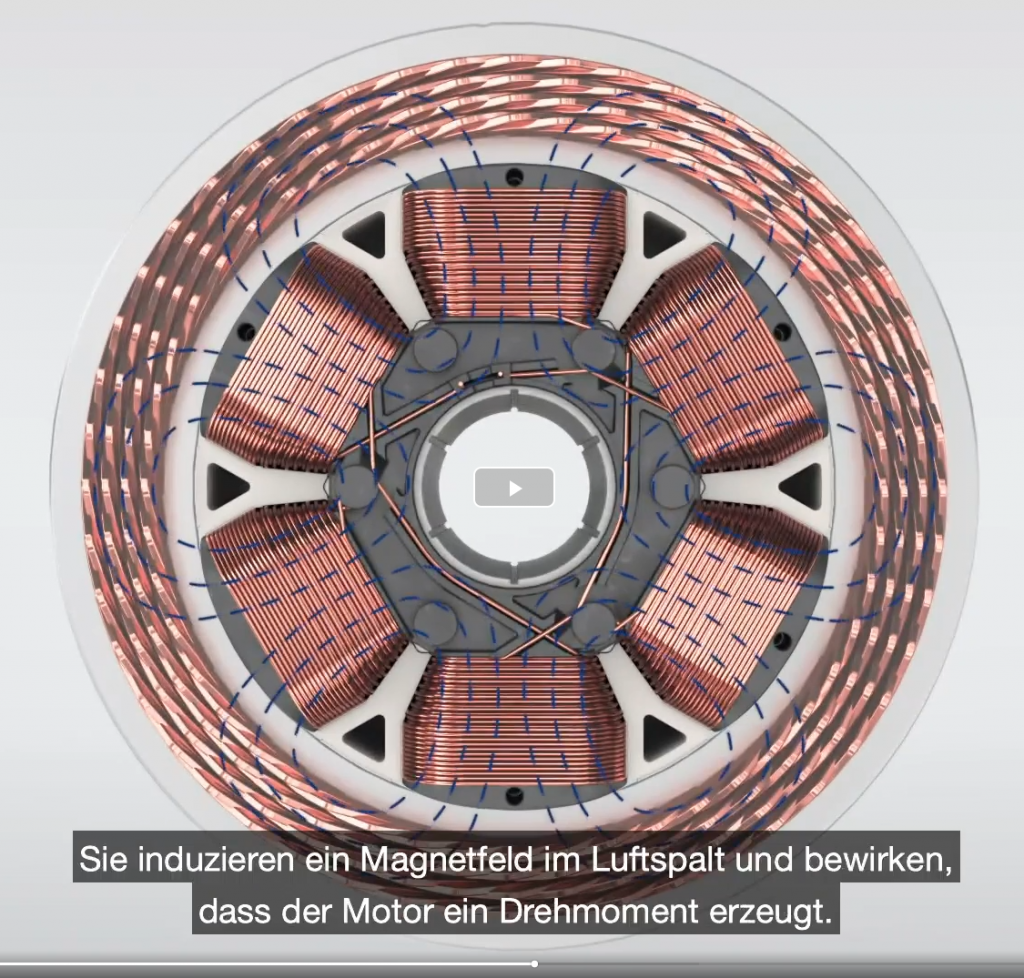
The motor appears to be what is commonly called a wound-field synchronous machine.
Simply put, each rotor pole has a coil, wound around an iron (electrical steel to be exact) pole-piece. Together, these coils form the field-winding. The field winding is excited with DC current, exciting the rotor field.
The stator then has a normal 3-phase AC winding, producing a rotating stator field. This field interacts with the rotor field, producing torque.

And finally, since it’s a synchronous machine, the stator field must rotate at the same speed as the rotor (very short transients aside, when the rotor angle with respect to the stator field may change).
The principle of operation is nearly identical to a permanent magnet motor. The only difference is the excitation – in a PM motor, the magnets would replace the field winding.
How the motor is excited
Perhaps the most interesting bit of tech is how the field winding is excited in the first place. Remember, it needs DC current to work.
The simplest approach would be to have brushes on the rotor shaft – two sliding electric contacts, transferring current. This solution is simple, but wears out with time, and can produce carbon (or other) dust that can cause issues in time.
Mahle’s solution is to, well, not use brushes. It is marketed as ‘wireless inductive power transfer’, which I guess is technically accurate, albeit not really standard language for this type of application.
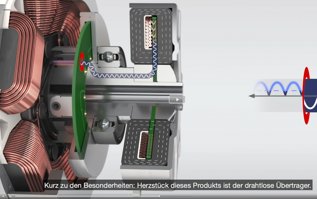
Anyways, a picture tells more than a thousand words here.

The solution appears to be to have a second, small electrical machine connected on the same shaft. On the rotor side, this machine has a winding, producing AC voltage, which is then rectified into a pulsating DC voltage and supplied to the field winding. The field winding then, being very largely inductive, nicely filters this into an almost-DC current.
This approach has long been used in large (MW-level) synchronous generators. In that application scope, the smaller machine is typically called an exciter, being responsible for exciting the field winding and all.
However, traditional exciters are typically of radial-flux topology. Furthermore, I THINK (my former ABB colleagues, please forgive my ignorance) the stator-side of a traditional exciter is normally supplied with DC current, while the rotor side would have a 3-phase winding.
Mahle’s solution is a bit different, for a good reason. They could have used a radial-flux exciter, with a 3-phase rotor winding, yes. What they couldn’t have done is use a DC winding on the stator-side of the exciter – it wouldn’t be able to excite the rotor at standstill. A rather huge drawback for a traction motor.
So, what they seem to have instead is a single-phase axial-flux AC exciter, with a flux path that one might call homopolar (dashed lines in the picture).
Simply put, the stator side of the exciter is fed with an AC current. The resulting pulsating flux couples the rotor-side winding of the exciter, and is then rectified into that aforementioned DC current.
There are some nice things about this.
Firstly, the exciter is (or appears to be, at least) single-phase, meaning you save a few power electronic components compared to a 3-phase system.
Secondly, due to the homopolar flux path, its operation is independent of the rotor rotation speed, which probably makes control easier, and limits the voltage range required.
Finally, the rotor of the exciter is coloured green in the video. This might be a coincidence, or it might imply it’s based on PCB technology, or it might be a conscious marketing choice to ride on the current hype-fame of PCB-based stator technologies.
What the motor isn’t
If I have to read the term ‘switched reluctance’ one more time, I’m gonna explode.
Switched reluctance machines are waaaaaay overhyped right now. I’d say they have replaced axial-flux as the go-to buzzword. Both can be good technologies, but neither is a magic solution that works the best everywhere, every time. And no, Tesla is not using a switched reluctance machine, either. I know Musk tweeted about it, but I’m 99 % sure he confused the abbreviations SRM and SynRM, the former being for a switched reluctance and the latter for synchronous reluctance machine. Tesla is using the latter, with PM assistance (PMaSynRM – not really catchy). You could also call it an IPM, the distinction is a line drawn in the sand, in the dark, in a sandstorm. But I digress. End-of-rant.
People probably see the rotor field-winding, and (incorrectly) associate it with the concentrated winding seen in switched-reluctance stators.
Also, I’m rather sure the motor does not have a concentrated winding in the stator. The renders in the video strongly imply a hairpin winding with perhaps four conductors per slot, but that might also be just a marketing tactic.

Looks like hairpin to me.
What the motor is good at
Compared to other topologies, the motor does have some more-or-less unique benefits.
There are no permanent magnets. That’s obvious. It may or may not be a price benefit (depends a lot on the application), but it certainly is a supply-chain benefit.
Field-weakening is easier compared to PM machines. In PM machines, you have to fight the PM field with stator current, to be able to supply the motor with the voltage you have available from your vehicle battery. In a field-wound motor, you simply decrease the field-winding current.
Fail-safety compared to PM motors. A short circuit, be it in the stator winding or on the inverter side, occurring at high speed is problematic to say the least. The motor will start acting as a brake, with most of the energy dumped into the short circuit location. In this motor, you can just switch off exciter.
Better power factor compared to induction and synchronous machines, most likely, at most operating points.
Better peak-torque / rated efficiency tradeoff compared to reluctance machines, I assume. Reluctance-type machines have to balance easy excitation of the airgap field (= short airgap length) at nominal loads with not oversaturating the motor at peak torque (= larger airgap). The same contradiction does exist in wound-field machines to a degree, yes, but it is somewhat alleviated by the saliency (magnetic asymmetry) of the rotor. Simply put, thanks to the poled structure of the rotor, the field is easy to excite along the field-winding axis, but harder along the perpendicular direction (mid-way between poles), which is where the stator field will mostly lie.
Lower rotor losses compared to an induction motor, I guess (haven’t done the math thoroughly). For minimal rotor losses, the stator and rotor current vectors should be perpendicular (at least if we neglect rotor saliency). This is not possible in an induction motor (although it does get close), but can be easily achieved in a wound-field machine. Even if the impact on efficiency were small, losses in the rotor are much harder to cool compared to the stator.
What the motor is not good at
Larger rotor losses compared to reluctance and PM machines.
Poorer peak torque compared to induction machines and possibly PM machines, too. Not necessarily the case, but there is a tradeoff between lower excitation losses (short airgap) and large peak torque without oversaturation (long airgap). Interior-PM machines also face the same issue, mind you, but in induction machines the rotor cage does a good job at keeping oversaturation at bay (until leakage fluxes become problematic).
Check out EMDtool - Electric Motor Design toolbox for Matlab.
Need help with electric motor design or design software? Let's get in touch - satisfaction guaranteed!

I would ask you to look at the technology on the CR Flight website crflight.com. You obviously understand a lot more about motor design than I do, but I would be curious to know where you would take this technology. Simply put, it is a direct electrical connection that can handle high amperage, high voltage, and high rpm without actually touching.
hello, How Can I contact with You? I am working about an electric motor too
Thanks for your kind explanation and insights .