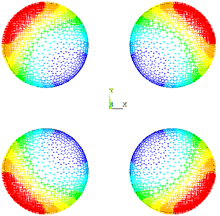
Simulation of eddy current losses in a stranded winding
Straight to business today: check out this animation I made!
See? It has colours and crap! How awesome is that??
In all seriousness, though, the animation visualizes the current density in the winding of an electrical machine. The winding is stranded, meaning it’s composed of several parallel-connected subconductors. The animation shows less than two dozen of them, near the opening of the first slot. In the entire slot, there are more than one hundred.
Details
Here are some details for you:
- A 500 kW cage induction motor was simulated with time-stepping FEA.
- Backward Euler was used for time-stepping.
- The nonlinear system was solved with the Newton-Raphson method.
- The moving band method was used for rotating the rotor.
- The machine was supplied with pulse-width modulated voltage, using the fairly typical sine-triangle comparison. The switching frequency was set to 2000 Hz.
- To actually, you know, model the eddy current losses, the entire winding was modeled. In other words, no uniformity assumptions here.
- 800 time-steps per period of supply voltage were used.
Interpretation
This particular winding is an interesting one for two reasons. First of all, it’s stranded, meaning it might suffer from circulating current losses. For those too lazy to click a link, this simply means that the total phase current is unevenly distributed between the parallel subconductors. This will obviously increase the resistive losses.
On the other hand, the wires used are still relatively thick. After all, it’s a large machine, and the number of subconductors is not that large. This means that the stranding might work less than perfectly at suppressing the actual eddy current losses.
Now, an important distinction has to be made. Circulating currents refer to the uneven distribution of total current between parallel conductors. By contrast, eddy currents relate to an uneven current density distribution within a single conductor. Depending on what causes the latter non-uniformity, eddy currents can be further divided into skin- and proximity effects.
In this case, both phenomena are clearly visible. Overall, the slots on the left side, near the slot opening, tend to have a higher average current density. This is probably due to them carrying a larger total current. In other words, circulating currents in play.
By contrast, the proximity effect is mainly responsible for the current density getting squeezed into a line, going through the center of each conductor. This is clearly visible too, in the red-yellow bands appearing in the animation.
These high-current-density bands seem to be traveling roughly vertically, most of the time. This can probably be attributed to the main leakage flux, crossing the slot in an almost perpendicular fashion.
However, also circular patterns can be seen at times. These are quite typical for conductor bundles in free space, with no iron components nearby. A simple example can be found below.

PWM Effects
As mentioned, the machine was supplied by a very simple PWM voltage. That simply means that the supply voltage of each phase will jump back and forth between its positive and negative peak value. At most, this can happen 2000 times per second, but in practice, things are a bit more gentle. But not much.

Anyway, these voltage switches are very clearly visible from the current density plot, too.
Remember those dense-current bands suddenly appearing?
Voltage switches. Indeed, a sudden change in the supply voltage will also start to increase or decrease the machine currents at a fast pace. A change in current obviously changes the nearby leakage flux. This drives the currents in the neighbouring conductors away from the first current, and vice versa.
And the effect of these switches is not limited to one phase. The simulated machine has a chorded winding, and the plot used for the animation has coils of two different phases going through it.
Indeed, of the loss bands you see, roughly half were caused by voltage switches in the illustrated phase. The remaining were due to the other phase, residing outside the figure on the right side.
Significance
These findings are actually somewhat surprising. Circulating currents are quite widely believed to only be significant in machines with a high supply frequency. That could mean actual high-speed machines or multi-pole permanent magnet machines such as those used in wind generators or electric vehicles.
By contrast, 50 Hz machines are typically assumed free from them. Indeed, their stranded windings are normally modeled by a uniform equivalent current density. This, of course, leaves even the proximity effects unconsidered.
These findings, albeit extremely preliminary, suggest this practice might be misguided. Both of circulating currents and proximity effects seem to cause small but significant losses. They might not influence the performance of the machine very much, but they’ll certainly cause it to run hotter.
Simulation Method
By the way, there’s a reason why people often use the aforementioned uniform current density. Modeling a stranded winding via traditional means is costly – it takes long. See for example here and here.
Indeed, I didn’t do that either.
Instead, I used a domain-decomposition type approach that I stole and perverted developed for that particular purpose. Compared to the just blindly meshing the winding, this new method seems to be approximately 50 times faster.
However, that’s the subject of an upcoming article of mine. So, no more of that for now – sorry but not sorry! 🙂
In the meantime – see ya!
-Antti
Check out EMDtool - Electric Motor Design toolbox for Matlab.
Need help with electric motor design or design software? Let's get in touch - satisfaction guaranteed!

