Numerical torque computation 101
Engineering is an error-critical field. Frak up, and there will be consequences. These can range from wasted time, to ill-performing prototype, to downright catastrophic. Thus, preventing and eliminating mistakes pays off big time in the long run. One approach is to verify your calculations by one or more alternative methods.

For electric motors and generators, one of the most (if not the) most important characteristic is its torque. So, we’ll be next looking into several numerical torque computation approaches.
We’ll begin with numerical methods. (Worry not – analytical methods are up next!) Because, well, numerical analysis is handy. Having the computer do the heavy lifting for you may not contribute much to your understanding, but at least you can trust your results. Or can you?
Maxwell stress tensor
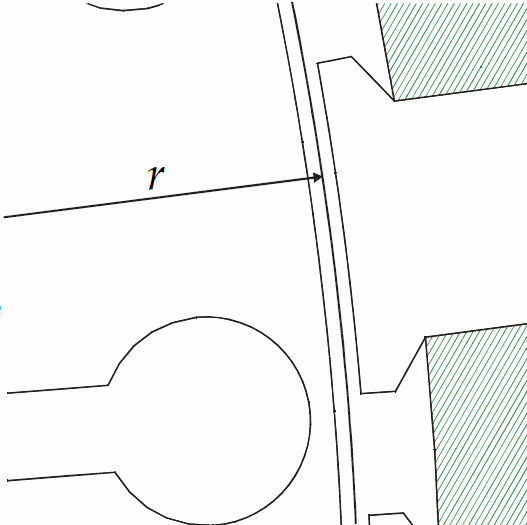
Often, the Maxwell stress tensor method is used to obtain the torque from the results of finite element analysis. In this method, the torque is computed by integrating the air-gap flux density along some circle enclosing the rotor. (In 2D – think a surface in 3D.)
Thus, the basic sanity check here is to try circles of different radii. They should give the same result, but in practice they almost never do. So, some deviation is to be expected, as we are dealing with an imperfect approximation after all.
However, trying different radii can also reveal hidden error sources.
For example, many commercial software packages use the so-called sliding interface method for moving the rotor. Now, if the integration circle happens to lie exactly on the surface, the results can go haywire. If they actually do go or not, depend on the software in use, the alignment of the planets, and so on. In other words, always check.
Weighted stress tensor(s)
One way to improve the accuracy of the stress tensor method is to average a large number of different integration paths.
Often, the so-called Arkkio’s method is used for this purpose. In this method, the torque is computed by a surface integral, instead of a line integral. (Or volume instead of surfacem in 3D) Hence, numerical ripple can be expected to cancel itself out, largely.

The method is a special case of the so-called weighted stress tensor (or eggshell) method, and works really nicely for cylindrical airgaps.
In Arkkios method, the weighting function is, in effect, specified manually, so that its gradient is perfectly radial. By contrast, the eggshell method uses a numerical approximation, resulting in numerical noise.
However, some choices remain even here. For instance, the entire airgap can be used as the integration surface, or only parts of it. (From mid-gap to stator, for instance.)
Furthermore, if rotor motion is modelled by the moving band method, and a multi-band airgap mesh is used, several new options appear. The motion can be applied to any of the bands, which may or may not be included to the torque integral. My friend and colleague Bishal Silwal has published extensively about this topic.
Power balance
Yet another option is to use the power balance method. In this approach, resistive losses are first subtracted from the input power. The remainder then consists of the change in the energy stored in the magnetic field, and the mechanical power. The former averages to zero over one period, leaving only the latter. From it, torque is obtained by simply dividing with the speed. (For torque ripple or transient performance, the magnetic energy has to be computed and differentiated, though.)

Other options
Coulomb’s method is yet another way based on integrating something in the airgap. It’s somewhat more complex than the stress tensor, but widely used nevertheless.
Finally, the airgap element method is based on not meshing the airgap at all. Instead, the airgap magnetic potential is written as an analytical series solution, and coupled to the FE solution on the boundaries.
Theoretically, this results in a very accurate field solution in air. Correspondingly, torque numbers should be good, too. Of course, inaccuracies in the stator and rotor field are also somewhat reflected in the airgap, too.
However, the biggest downside is the computational cost of the method. Specifically, the air-gap element approach results in a so-called dense block in the linear system of equations. This, in turn, can greatly increase the CPU time needed to solve the problem. Hence, more time spent idling in front of a computer, hearing its fans shriek.
Conclusion
Knowing the torque of an electric motor is kinda important. Even when using numerical analysis, it makes sense to double-check your results by using an alternative computation method. This final sanity check can save lots of time, money, and frustration – if performed before committing to prototyping, or let alone production.
Next up – analytical methods!
Check out EMDtool - Electric Motor Design toolbox for Matlab.
Need help with electric motor design or design software? Let's get in touch - satisfaction guaranteed!
