Numerical orientation of a polygon continues
Hi again! Last time, I wrote about how I was given some a very basic FEM mesh, and had to determine the magnetization direction of a permanent magnet from it. In simpler words, I had a bunch of triangles determined by their corner coordinates, I knew their union formed a rectangle, and I had to determine the long and short axes of it. The direction of a rectangle, you could say.
I concluded that the axes are the eigenvectors of the matrix ![]()
 ,
,
where ![]() denotes the area that the magnet occupies.
denotes the area that the magnet occupies.

Matrix evaluation
Now, the remaining problem is how the evaluate the matrix entries. Luckily for me, it can be easily done with some basic finite element codes that I already have. You see, in finite element analysis, we approximate the solution ![]() as a weighted sum
as a weighted sum
![]() .
.
Here, ![]() are the unknown coefficients to solve – let’s us not concern ourselves with them now.
are the unknown coefficients to solve – let’s us not concern ourselves with them now.
More important for today are the shape functions ![]() . They are some scalar-valued (in our case at least) functions of the position
. They are some scalar-valued (in our case at least) functions of the position ![]() , each associated with a certain node
, each associated with a certain node ![]() . The main point about them today, however, is that I know how to manipulate them inside and out. That’s the side-effect of having a functioning FEM library.
. The main point about them today, however, is that I know how to manipulate them inside and out. That’s the side-effect of having a functioning FEM library.
You see, each shape function ![]() gets a value of 1 at the point
gets a value of 1 at the point ![]() corresponding to the node
corresponding to the node ![]() , and a zero value at the remaining nodes. Thus, we can do the following stupid-looking substitution
, and a zero value at the remaining nodes. Thus, we can do the following stupid-looking substitution
![]()
![]() .
.
In other words, we can express the ![]() – and
– and ![]() -coordinates with the shape functions and the coordinates of the nodes
-coordinates with the shape functions and the coordinates of the nodes ![]() .
.
That dummy-relation can then be utilized the calculate the integrals for the ![]() matrix. For example, we can write
matrix. For example, we can write
![]()
as
![]() .
.
This, in turn, can be written as
![]() ,
,
where ![]() contains the x-coordinates of the nodes
contains the x-coordinates of the nodes
![]() ,
,
and the newly-introduced matrix ![]() has the entries
has the entries
![]() .
.
This is the so-called mass matrix, one of the most important matrices used in FEM. In other words, given the mesh data – which we have – assembling it is no problem at all. With the mass matrix ![]() , the other matrix
, the other matrix ![]() used in the axis calculation can be compactly written as
used in the axis calculation can be compactly written as
![]() ,
,
the vector ![]() containing the y-coordinates of the nodes.
containing the y-coordinates of the nodes.
Centering
Bear in mind one thing, however. Last time I assumed that the permanent magnet – the domain ![]() – is “centered” around zero in some way. An exact definition would be that the center of mass of the magnet is in the origin. In other words, we want
– is “centered” around zero in some way. An exact definition would be that the center of mass of the magnet is in the origin. In other words, we want
 ,
,
and equivalently for ![]() . Using a similar reasoning as above, this can be written as
. Using a similar reasoning as above, this can be written as
![]() .
.
Here, ![]() is a vector of all-ones, and
is a vector of all-ones, and ![]() is the prototype finite element load vector
is the prototype finite element load vector
![]() .
.
Once the center of mass has been calculated, the centered coordinates can be obtained by substituting
![]() and
and
![]() .
.
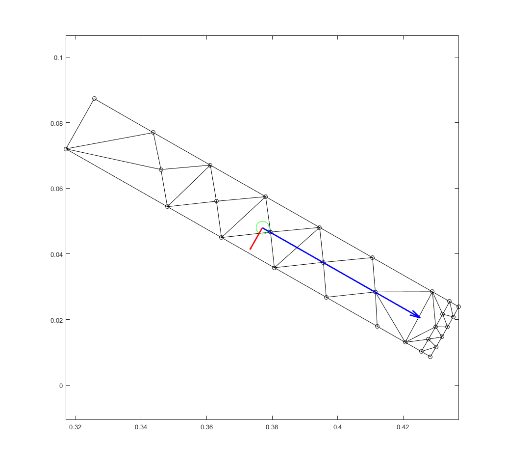
This has been illustrated in the figure you already saw last time. Indeed, the green circle denotes the center of mass of the magnet.

Conclusion
So all in all, a problem stemming from FEM – the direction of a rectangle, or PM – could easily be solved with FEM codes. Kinda boring.
However, on a deeper level the problem itself has more diverse, more multi-disciplinary aspects than this.
Firstly, the problem of determining the orientation of a rectangle is nothing else than computational geometry. Secondly, finding the previously-mentioned vector-matrix-vector product maximum was pure linear algebra.
And finally – and this is the most interesting one for me – the problem could also be approached from a purely mechanical angle. The rectangle could be interpreted as a solid object, and its long and short axes as its principal axes. Indeed, this principal axis interpretation ties our weird ![]() matrix to the inertia matrix often used in mechanics.
matrix to the inertia matrix often used in mechanics.
Mechanical engineers – let’s say we’re even now, shall we?
UPDATE: Check out this post for another possible application example of the algorithm!
-Antti
Check out EMDtool - Electric Motor Design toolbox for Matlab.
Need help with electric motor design or design software? Let's get in touch - satisfaction guaranteed!
