How to numerically determine the long axis of a polygon?
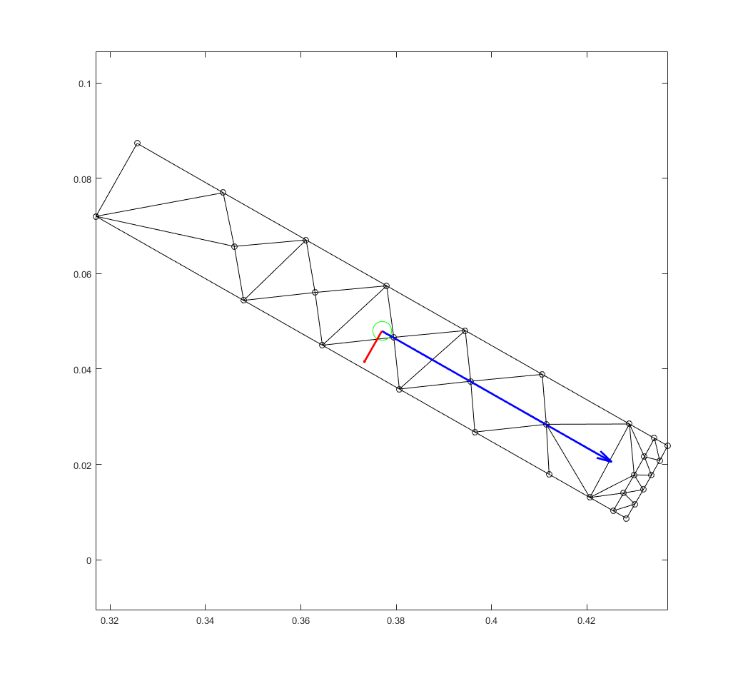
This week, I tweeted some indecipherable-looking scripplings of mine. Although probably not apparent at first glance, I was dealing with computational geometry. Again. This time however, it was not point-in-polygon, but determining the direction to which a 2D rectangle is pointing to from raw, numerical data.
What? You need more information?
Some people….
Anyway, here goes:
Background
As you know, I do most of my research on finite element analysis (FEM) in Matlab. This is mainly because my work mainly deals with developing the method itself, rather than using it as a tool. Thus, ease of use is of more importance than speed (although Matlab can be quite fast indeed if you know what you are doing).
However, this week I had to import some machine models from an in-house finite software into my Matlab software. I didn’t want to dig deeply into FORTRAN code, so I only had access to some basic data. Think nodes, elements and material data, and not much else.
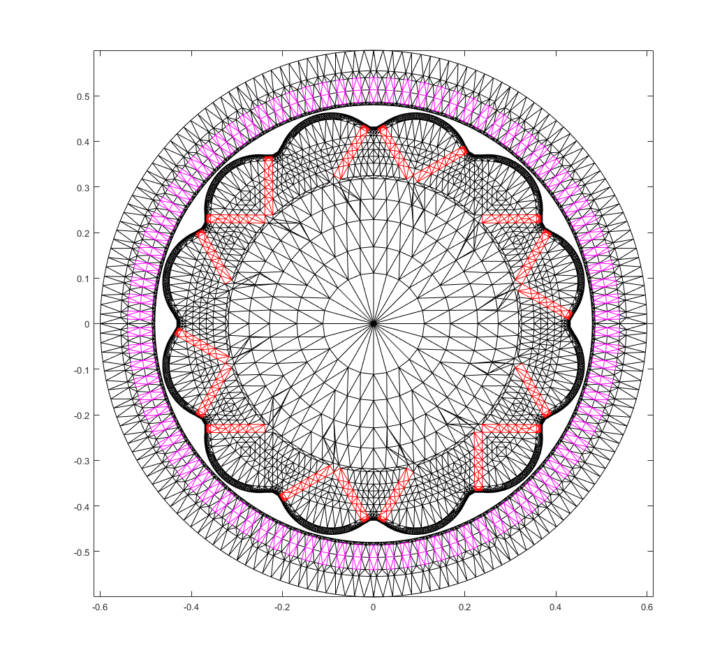
Below, you can find an illustration of what I’m talking about. In the figure you see a 12-pole permanent magnet machine, with the stator slots highlighted in magenta, and some of the magnets in red. These were easily determined from material data: conductors are usually copper, and magnets are made from magnet-stuff.
However, what was not easy was determining the direction a particular magnet is magnetized to. Of course, this is easy to do visually – in most machines any particular magnet is magnetized along the short axis. In other words, find the longest side of the magnet, and the magnetization direction is perpendicular to it.
But, I might be forced to deal with a large number of machine models in the near future, so I wanted to keep things as automatic as possible. Ergo, relying on eyes only was out of the question.
Process
So, I had to determine the long and short axes of a rectangle in a purely numerical way. How to do that?
Well, let’s first assume that the magnet is “centered” (we’ll soon see in what sense) around the origin. Then, for the long axis, it would be sufficient to determine a particular unit vector ![]() . This vector would have to be such that the mean distance is minimized between all points
. This vector would have to be such that the mean distance is minimized between all points ![]() inside the magnet, and the line determined by
inside the magnet, and the line determined by ![]() (and going through the origin).
(and going through the origin).
Let’s, however, first consider a single point ![]() only. Since
only. Since ![]() is an unit vector, the closest point
is an unit vector, the closest point ![]() to
to ![]() on the aforementioned line is
on the aforementioned line is
![]() .
.
The squared distance between that point and ![]() is then
is then
![]()
![]()
![]() ,
,
where the relationship ![]() has been utilized between the second-last and last lines.
has been utilized between the second-last and last lines.
Then, to minimize the total squared distance
![]()
over the surface area ![]() of the magnet, it is sufficient to maximize the latter term
of the magnet, it is sufficient to maximize the latter term
![]() .
.
This, in turn, can be written as a more familiar-looking surface integral
![]() ,
,
where ![]() are the components of
are the components of ![]()
![]() .
.
This integral, in turn, can be expanded into
![]()
and re-written as
 .
.
Solution
So let me emphasize this last result. What I needed to do was determine an unit vector ![]() that maximises an expression of type
that maximises an expression of type
![]() .
.
Can you see it now?
Almost-by-definition, the long axis ![]() would of course be the eigenvector of
would of course be the eigenvector of ![]() associated with the largest eigenvalue! And even more nicely, the more interesting short axis would be the second eigenvector. And both of these could be easily computed with Matlab (or any mathematical software for that matter), once the matrix
associated with the largest eigenvalue! And even more nicely, the more interesting short axis would be the second eigenvector. And both of these could be easily computed with Matlab (or any mathematical software for that matter), once the matrix ![]() was calculated.
was calculated.

Research often brings us to surprising matters, doesn’t it? Indeed, I’ve written about this particular topic at least once before.
Check out part 2 of the post here!
-Antti
Check out EMDtool - Electric Motor Design toolbox for Matlab.
Need help with electric motor design or design software? Let's get in touch - satisfaction guaranteed!

